


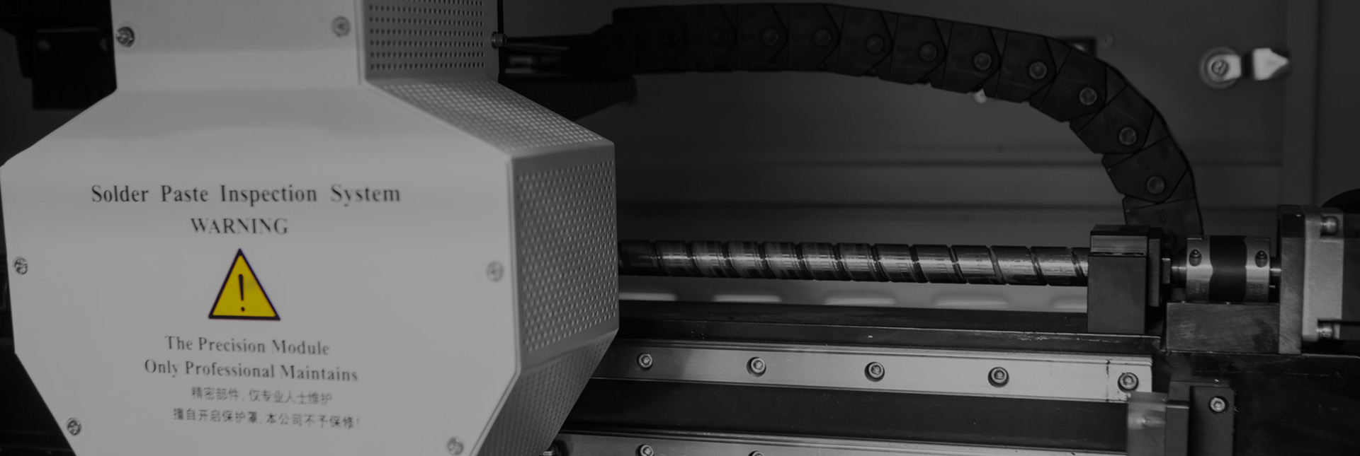
An SMT testing device that uses the principle of optics to calculate the height of solder paste printed on PCB board by triangulation
3D-SPI In-Line Solder Paste Inspection V860 (Standard Model)
Description
High precision control platform
The motion platform adopts the servo motor and high precision ball screw structure, high-speed, stable, no vibration, no noise. With the high precision grating closed-loop feedback system
High definition, high speed camera
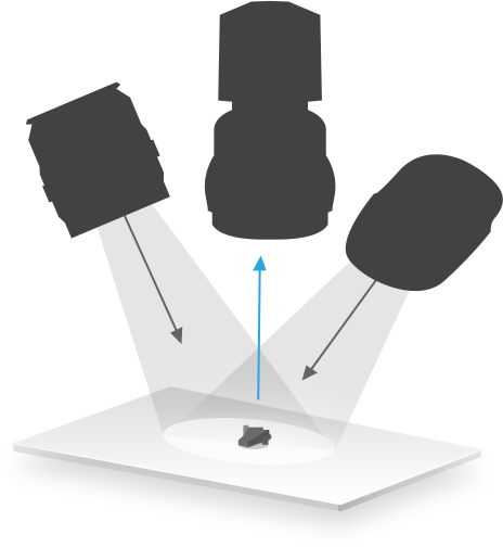
High frame rate industrial camera and lens to achieve the high speed photography;
Self-owned intellectual property RGB light can get 2D & 3D true color image which look realistic;
The GPU parallel processing technique can greatly improve the speed of calculation and detection。

Double projective structure grating system
The N step phase shifting algorithm bassed on the white light moire fringe technique, providing 1um high inspect accuracy
There are multiple grating for option to deal withreflection and shadow
Humanized machine interface
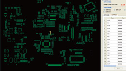
The software can create the PAD information automatically by input the CAD file ( in dxf ) or the Gerber file ( in RS274-D、RS274-X ), only need to set inspect parameters to finish the programming.
True color 3D image
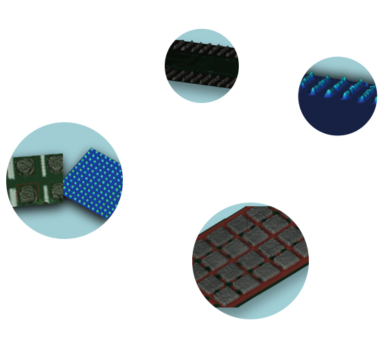
Phase measuring profilometry ( PMP ) based on the sinusoidal motion projection by structure grating,
the multiple images by discrete phase shift,to calculate the phase distribution by multi- phase,the triangulation and so on to get the high-precision outline and volume of the object to be measured。 shown in 3D true color
Fully diversified functional templates
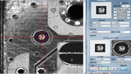
It can import Gerger, CAD and other data through offline programming software for remote programming, and the programming time does not exceed 5 minutes. For the case where there is no mark point data in the Gerber file, or when the bare board is programmed, it is possible to define a virtual mark and then set any real mark point on the PCB board as the detection anchor point.
Detailed SPC analysis system
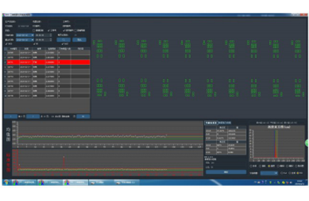
SPC analyzed the feedback of test informations to promote the improvement of the process, in order to prevent adverse.
The operator can view test report visually by pie chart or column chart.
And the statistical information can be exported in Html, Excel or Image format.

Specification
| Items | VCTA-V850 | VCTA-V850L | |
|---|---|---|---|
| Camera | Digital High-Speed CCD 5M Pix | ||
| Lamp-house | Ring R/G/B LED and White LED | ||
| FOV | 36*36mm(18μm) | ||
| Speed Per FOV | <0.6s | ||
| Items | Solder/Red gum: Volume、Area、Height、Shape、Shift、Bridge、Overflow | ||
| Area Range | 0.15mm×0.15mm~10mm×10mm | ||
| Height detection resolution | 0.37μm | ||
| Height Accuracy on Certificated Target | 1μm | ||
| PCB Transmit | Bottom-up fix; Auto transmit and width correct based on SMEMA signal;Conveyor Height: 900±200mm | ||
| PCB Size | 50x50mm`330x250mm 80x80mm`460x510mm | ||
| Controlling&Tecognizing | Characteristics | Dual 3D Projection (Single optional) avoid shadow and reflection | |
| Operation | Graphic programming, Chinese, English | ||
| Result | 2D/3D true color | ||
| MARK | 2common Marks can be chosen,or muti-marks can be chosen and skip function of array boards | ||
| Programming | Gerber 274D/X、CAD,Offline program,Bare Board Teach | ||
| SPC | Offline SPC | Support | |
| Chart | Any Time Chart | ||
| Computer | Industrial computer:Intel 4 Memory:8G, Hard disk: 1TB | ||
| Display | 19 inch TFT | 24 inch TFT | |
| Machine Dimensions | 110x110x165cm | 120x120x165cm | |
| Weight | ~650kg | ~850kg | |
| Power Supply | AC220V±10%,50/60Hz,1200W |


Reviews
There are no reviews yet.